 Loading... Please wait...
Categories
How to Reduce Noise in Electronic Circuits
Posted by Schmartboard on Jun 18th 2025
Clean Signals Start with Smart Design—Here’s How to Achieve It
Noise is one of the most frustrating challenges in electronics. Whether you're designing an audio amplifier, sensor interface, or digital communication system, electrical noise can disrupt performance, degrade signals, and create hard-to-trace bugs.
But here’s the good news: with a few smart strategies—and the right prototyping tools like Schmartboard—you can drastically reduce noise in your circuits from the start.
What Is “Noise” in Electronics?
In simple terms, noise is any unwanted electrical signal that interferes with the desired operation of your circuit. It might appear as static in audio circuits, glitches in digital systems, or voltage fluctuations that throw off sensitive components.
Common sources of noise include:
-
Electromagnetic interference (EMI) from nearby devices or power lines
-
Poor grounding or power supply decoupling
-
Long, unshielded wires acting like antennas
-
Crosstalk between closely spaced traces
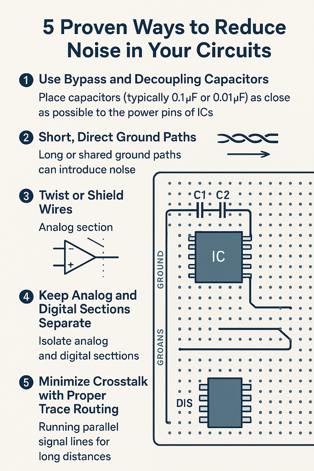
5 Proven Ways to Reduce Noise in Your Circuits
1. Use Bypass and Decoupling Capacitors
Place capacitors (typically 0.1μF or 0.01μF) as close as possible to the power pins of ICs to stabilize voltage and absorb transient spikes.
Tip: Schmartboard’s prototyping boards offer convenient pads and traces for clean capacitor placement near power rails, making good layout easy.
2. Short, Direct Ground Paths
Long or shared ground paths can introduce noise. Use a ground plane if possible or ensure your grounds are short and don’t share return currents.
With Schmartboard, ground paths are clearly marked, and some boards even include ground planes for better shielding.
3. Twist or Shield Wires
When routing signals over longer distances, use twisted pair or shielded cables. This is especially critical for analog or high-frequency digital lines.
4. Keep Analog and Digital Sections Separate
Mixed-signal systems should isolate analog circuitry from noisy digital switching signals.
Schmartboard makes this easier with modular board layouts, so you can prototype analog and digital sections separately before integration.
5. Minimize Crosstalk with Proper Trace Routing
Avoid running parallel signal lines for long distances. If unavoidable, add ground traces between them or increase spacing.
On Schmartboard’s high-quality PCBs, trace spacing and layout patterns reduce the risk of accidental coupling and signal bleed.
Why Schmartboard Makes a Difference
Schmartboard isn’t just a prototyping platform—it’s a precision tool for engineers who care about signal integrity. Whether you're hand-soldering SMT components or designing a high-performance analog stage, these boards give you:
-
Clean, professional layouts
-
Easy-to-follow routing and labeled connections
-
Patented "EZ" technology for reliable surface-mount soldering
-
Specialized boards for analog, digital, mixed-signal, and power regulation circuits
Final Thoughts
Noise problems don’t have to be mysterious. With good practices and smart prototyping tools, you can build clean, stable, and professional-grade circuits—even at the prototype stage.
Start with the right foundation—start with Schmartboard.
Explore boards, kits, and tools at Schmartboard.com
Recent Posts
- » Do Inspect Solder Joints Under Magnification for Intermittent Issues
- » Don’t Assume Power Supplies Are Perfectly Clean
- » Do Choose the Right PCB Stack-Up Early to Support Signal Integrity
- » Do Route High-Frequency Signals with Controlled Impedance
- » Don’t Overcrowd the Board — Leave Room for Debugging