 Loading... Please wait...
Categories
How to Identify and Fix Bad Solder Joints
Posted on Jul 18th 2025
Whether you’re a seasoned engineer or a weekend electronics hobbyist, mastering the art of soldering is essential to creating reliable circuits. One of the most common issues that can cause malfunction or total failure in a circuit is a bad solder joint. Identifying and fixing these flaws early can save time, protect components, and ensure your project works as intended.
In this post, we’ll walk through how to spot bad solder joints, what causes them, and how to properly repair them. Plus, we’ll share how tools from Schmartboard can help make the soldering process easier and more forgiving—especially for fine-pitch components.
What Is a Bad Solder Joint?
A bad solder joint occurs when the connection between the component lead and the PCB pad isn’t secure or conductive enough. This can lead to intermittent behavior, high resistance, or complete loss of electrical connectivity.
Common types of bad joints include:
-
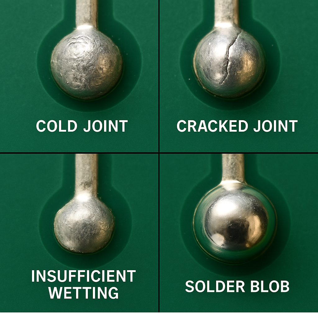
Cold joints – Appear dull or grainy; caused by insufficient heat during soldering.
-
Cracked joints – Tiny cracks that form over time due to mechanical stress or thermal cycling.
-
Insufficient wetting – Solder doesn’t fully cover the pad or component lead.
-
Excess solder (solder blobs) – Can cause short circuits, especially in fine-pitch components.
-
Lifted pads – Caused by excessive heat or force, damaging the PCB.
How to Identify Bad Solder Joints
Visual inspection is the first step. Use these tools and techniques:
-
Magnification tools – A magnifying glass or microscope helps catch small defects.
-
Proper lighting – Bright, diffuse light reveals surface texture and shine.
-
Continuity testing – A multimeter in continuity mode can detect broken connections.
-
Wiggle test – Gently moving components with tweezers may expose loose joints.
What to Look For:
|
Type of Defect |
Visual Clues |
|---|---|
|
Cold Joint |
Dull, gray, uneven surface |
|
Cracked Joint |
Hairline fractures around the lead |
|
Insufficient Wetting |
Partial solder coverage on pad or lead |
|
Solder Blob |
Rounded, excessive solder not forming a "volcano" shape |
|
Lifted Pad |
Pad peeling or missing from PCB surface |
How to Fix Bad Solder Joints
Once identified, repairing bad joints is straightforward with the right technique:
-
Desolder if Needed: Use a desoldering braid or a pump to remove excess or faulty solder.
-
Apply Fresh Flux. Flux helps solder flow and bond properly. Don’t skip this step.
-
Reheat and Resolder Use a clean, temperature-controlled iron. Heat both the pad and the lead before applying solder.
-
Inspect Again Confirm that the joint is shiny, smooth, and shaped like a small cone or volcano.
How Schmartboard Makes Soldering Easier
Soldering surface mount components can be intimidating, especially for beginners or when working with very fine-pitch ICs. Schmartboard offers patented prototyping boards with pre-tinned, solder-trace technology that dramatically improves solderability.
These boards guide solder into place and reduce the risk of cold joints or bridging. For those struggling with alignment or heat management, Schmartboard products are a game changer. They’re particularly useful for:
-
SMD component prototyping
-
Educational labs
-
Hobbyist and maker projects
-
Fast, reliable testing and debugging
With Schmartboard, the learning curve is reduced and the results are cleaner, more reliable connections—especially when soldering under a microscope or without steady hands.
Final Tips
-
Always use clean tools and high-quality solder.
-
Don’t rush—allow enough heat and time for proper flow.
-
Practice on scrap boards before working on your main project.
-
If in doubt, reflow the joint. It’s better to spend a few extra seconds than to debug a failing board later.
Conclusion
Bad solder joints are one of the most common causes of circuit failure, but they’re also one of the easiest to fix—once you know what to look for. Armed with a little knowledge, good lighting, and the right tools (like Schmartboard's user-friendly prototyping platforms), you can tackle even the trickiest soldering jobs with confidence.
Happy soldering!
Recent Posts
- » Do Inspect Solder Joints Under Magnification for Intermittent Issues
- » Don’t Assume Power Supplies Are Perfectly Clean
- » Do Choose the Right PCB Stack-Up Early to Support Signal Integrity
- » Do Route High-Frequency Signals with Controlled Impedance
- » Don’t Overcrowd the Board — Leave Room for Debugging