 Loading... Please wait...
Categories
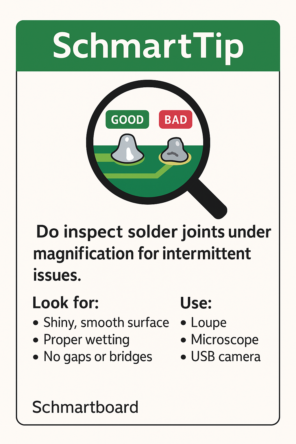
Do Inspect Solder Joints Under Magnification for Intermittent Issues
Posted by Schmartboard on Oct 26th 2025
A circuit is only as reliable as its connections — and in electronics, that means solder joints. Even the most perfectly designed PCB can fail if a single solder joint is cracked, cold, or barely making contact. The problem? Many of these flaws are too small to see with the naked eye.
That’s why one of the most important quality checks you can do is simple but powerful:
Do inspect solder joints under magnification for intermittent issues.
Why Magnification Matters
Solder joints are deceptively small. They might look fine under room lighting, but microscopic imperfections can lead to:
-
Intermittent connections — circuits work one moment, fail the next.
-
Open circuits — solder didn’t fully wet the pad or lead.
-
Cold joints — dull, grainy solder caused by insufficient heat.
-
Bridged pins — tiny solder blobs connecting adjacent pads.
-
Cracked joints — stress fractures that develop over time.
Magnification allows you to see the truth — the difference between a shiny, properly wetted joint and a weak one waiting to fail.
How to Inspect Solder Joints Properly
Here’s what to look for when using magnification tools such as a loupe, microscope, or USB inspection camera:
-
Shiny, smooth surface:
A good solder joint should have a concave, mirror-like finish — not dull or grainy. -
Proper wetting:
The solder should smoothly flow from the component lead to the pad, forming a natural curve. -
No gaps or voids:
Any visible cracks, pits, or voids indicate poor soldering. -
No bridges:
Adjacent pads or leads should not be connected by stray solder. -
Consistent size and shape:
Joints should appear uniform — uneven joints suggest inconsistent heat or solder volume.
Tools That Make Inspection Easier
-
10x–20x Jeweler’s Loupe: Portable and inexpensive for quick checks.
-
Digital USB Microscope: Allows high magnification and image capture for documentation.
-
Stereo Microscope: Ideal for rework stations and professional inspection.
-
Ring Light or Adjustable LED: Proper lighting reveals flaws you’d otherwise miss.
Common Causes of Bad Solder Joints
-
Insufficient or uneven heating.
-
Dirty pads or oxidized leads.
-
Using the wrong solder alloy or flux.
-
Moving the joint before cooling.
-
Excessive solder that bridges leads.
Recognizing these during inspection helps you correct the technique before problems repeat.
How Schmartboard Makes It Easier
At Schmartboard, we understand that soldering precision can make or break a project — especially for beginners or small-batch engineers. That’s why our Schmartboard prototyping products are designed to help you solder cleanly, consistently, and confidently.
-
Our patented “EZ” solder technology includes pre-tinned pads and raised traces, guiding solder flow automatically.
-
Ideal for SMD components, even under magnification — the joints form neatly with minimal effort.
-
You can focus on inspection and testing rather than rework and frustration.
When paired with proper inspection habits, Schmartboard helps you build professional-quality circuits right on your workbench.
Final Thoughts
Small defects cause big headaches. An intermittent connection can waste hours of debugging and lead to unreliable products in the field.
So before you power up your next board, take a moment to inspect those solder joints under magnification. It’s one of the fastest, easiest ways to ensure long-term reliability — and it’s a habit that separates careful engineers from careless ones.
Good connections are built, not guessed. Inspect, verify, and trust your work — the Schmartboard way.
Recent Posts
- » Do Inspect Solder Joints Under Magnification for Intermittent Issues
- » Don’t Assume Power Supplies Are Perfectly Clean
- » Do Choose the Right PCB Stack-Up Early to Support Signal Integrity
- » Do Route High-Frequency Signals with Controlled Impedance
- » Don’t Overcrowd the Board — Leave Room for Debugging