 Loading... Please wait...
Categories
From The Archives- Simple Step Motor Control
Posted on Aug 3rd 2011
8 Bit PIC® SchmartModule Work Shop
Simple Step Motor Control
By Bryan Lai
SchmartBoard
Introduction
This project uses a PIC16F886 to drive a 5-wire step motor.


Basic Step Motor Operation
Single Stepping (Single-Coil Excitation): This is the simplest stepping
mode. In this mode, each successive coil is energized and the motor
moves one full step at a time. Therefore, a motor with a step angle of
7.5 degrees will rotate through 7.5 degrees with each step. Here's how
single stepping works:

Pulse	Coil 1	Coil 2	Coil 3	Coil 4
1	1	0	0	0
2	0	1	0	0
3	0	0	1	0
4	0	0	0	1
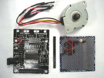
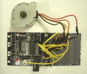
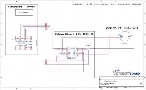
Schematic and Wiring Information Solder the SMD
chips, other through-hole chips, components and headers. EZ
SchmartBoard Technology will make it easy to solder the SMD chips. Then
refer to the schematic and use jumpers to wire the circuit together.
After programming the PIC, just plug in the 6~15V DC power and the
motor will start to rotate.

Sample Code
Demo code is written in Basic language for PICBASIC PRO™ Compilers Demo
version. Demo will rotate the motor clockwise and counterclockwise.
Between two rotations, the motor will stop around 5 seconds to ease
loading from the regulator. For constant rotating, external power is
recommended. IDE: Microcode Studio comes with PICBASIC PRO™ Compiler
Demo Version (FREE) Compiler: PICBASIC PRO™ Compiler Demo Version
(FREE) Link: http://www.melabs.com/pbpdemo.htm
Tips and Considerations • This demo shows one stepping method, you can use other methods later on for this hardware setup.
Components and SchmartBoards
8 Bit PIC® SchmartModule (710-0004-01), Pre-trace Through-hole
SchmartBoard (201-0001-01), Motor driver (L293D), 47-ohm resistor,
Step motor (M35SP-7T, Mitsumi) (Qty 2) 5” SchmartBoard Female Jumpers
and Headers (920-0006-01) For more info and purchasing, please
clink the links below. 8 Bit PIC® SchmartModule Pre-trace Through Hole SchmartBoard SchmartBoard Female Jumpers and Headers Software Code
Recent Posts
- » Do Inspect Solder Joints Under Magnification for Intermittent Issues
- » Don’t Assume Power Supplies Are Perfectly Clean
- » Do Choose the Right PCB Stack-Up Early to Support Signal Integrity
- » Do Route High-Frequency Signals with Controlled Impedance
- » Don’t Overcrowd the Board — Leave Room for Debugging
